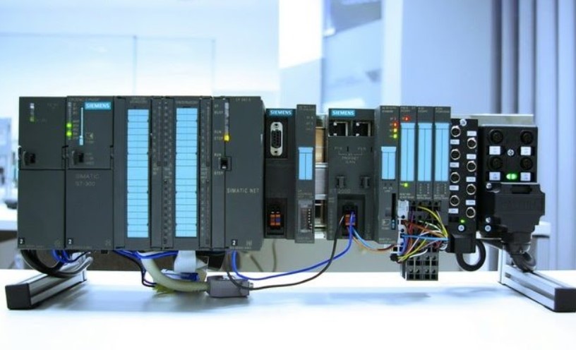
Siemens S7-300 PLCs related together with the usage of the MPI (Multi-Point Interface) interface. The Siemens MPI protocol is used by Siemens PLCs to speak with external devices. I favor renaming each of the seven PLCs. Here are the steps to accomplish that task. To get more detailed information you can visit shop.oem-automation.com.
First, join your MPI cable to the first PLC. I will be connecting my laptop to every PLC individually. Power up the PLC and open Simatic Manager. The “New Project” Wizard window will open. Just click Cancel to shut the window. Now click the Accessible Nodes icon on the toolbar. A window will open displaying the identification of the PLC you are connected to. My window is displaying MPI = 2(directly). Make a note of this tackle and close the window.
Next, we want to download a hardware configuration to the PLC. This is the place we will rename the PLC node address. There are probably a couple of special ways to do this – the following is how I accomplish this. All seven of my PLCs are identical models; therefore, I am using the identical hardware configuration. For obvious reasons, I favor giving every a different MPI node address. I have a venture file that contains all seven of my PLC applications and one hardware configuration file. I open the one hardware configuration file and then double click Hardware in the proper hand window. This will open the HW Configuration window. In this window, you should see your PLC with its MPI tackle given.
Remember when we clicked the Accessible Nodes icon and saw MPI = 2(directly)? My Hardware Configuration Window is displaying an MPI address of 7. Place your mouse cursor on the 7 and double click. Your CPU Properties window will open. It must open to the General tab. Look down and you will see Interface Type MPI with an address of 7. Click Properties and the MPI interface Properties window will open. Using the pull-down menu, pick your MPI node address and make positive the MPI (1) 187.5kbps is highlighted and click OK. You are now again on the CPU Properties window where you will see your tackle has changed. Click OK and you will go back to the HardWare window the place you can verify your MPI node tackle has changed.
You will now click the Save and Compile icon and then click on the download icon. The Select Target Module window will open. Click OK and the Select Node Address window will open. Here you will see the MPI node tackle you assigned earlier. You will need to click on the View button right beneath this. You will see the current node tackle appear, this should be equal to what you saw previously when you clicked the Accessible Nodes icon. Simply click on this quantity and you will see it appear in the MPI tackle slot under the Enter connection to the goal station. Click OK and the Download to Module window will open. Click OK and the Stop Target Modules window will open. Click OK and the “Do you want to begin the module?” window will open. Click Yes.


